Inquiry
Form loading...

What Is a Spin On Filter and How Does It Work?

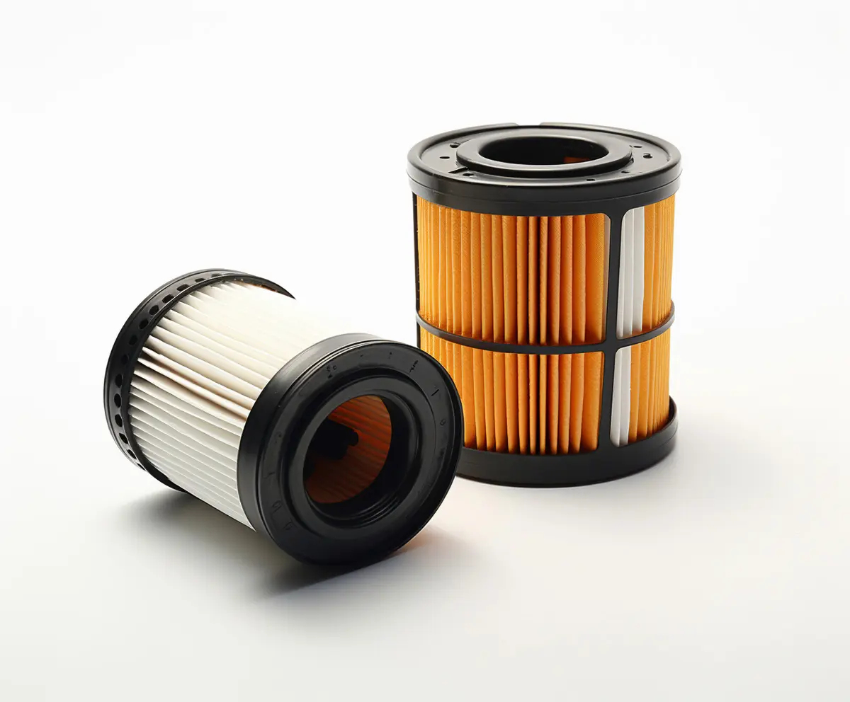
A Spin On Filter is a self-contained filter assembly used in engines, hydraulic systems, fuel circuits, and other fluid applications. It combines the filter media, metal housing, sealing gasket, and threaded connection in one replaceable unit. Unlike a cartridge element, the complete canister is removed during service. This design saves time. It also reduces contact with contaminated media.

Inside the housing, fluid enters through small inlet holes and passes across the filter media. The media traps particles such as dust, carbon, rust, and metal fragments. Cleaned fluid then moves through the central tube and returns to the system. Many models include an anti-drainback valve, which helps retain oil during shutdown. Some also contain a pressure-relief valve for cold starts or blocked media. These features sound minor. They protect expensive components.

In practical maintenance, correct installation matters as much as filter quality. A technician should confirm the part number, thread size, gasket diameter, pressure rating, and fluid compatibility. Applying a thin layer of clean fluid to the gasket can support proper sealing. Over-tightening may damage the gasket or housing. Under-tightening may cause leaks. The filter can appear sound while its media is already restricted. Therefore, replacement intervals should follow the equipment manufacturer’s guidance and actual operating conditions. Heavy dust, frequent cold starts, and high temperatures may shorten service life. A Spin On Filter is simple, but not foolproof. Choosing only by appearance or price can create avoidable risks. Careful inspection remains essential.
What Is a Spin On Filter and How Does It Work?

Defining Spin-On Filters: Purpose, Parts, and Common Applications

What Is a Spin-On Filter and How Does It Work?

Defining Spin-On Filters: Purpose, Parts, and Common Applications

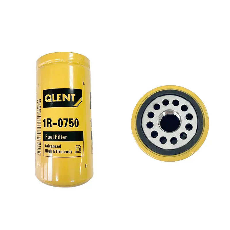
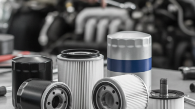
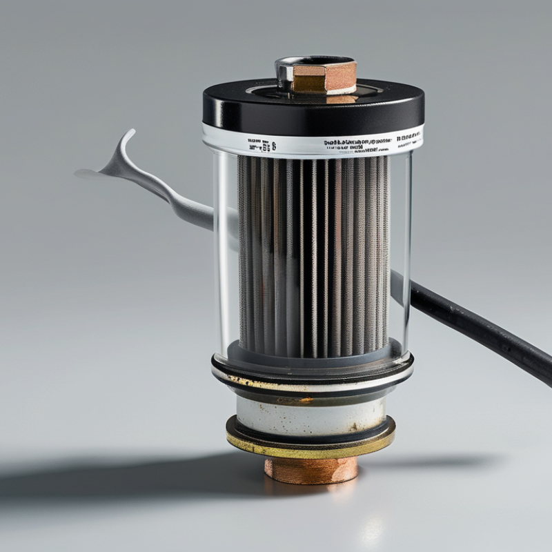
A spin-on filter is a replaceable filtration unit housed in a sealed metal canister. It removes dirt, metal particles, and other contaminants from circulating fluids. The filter threads directly onto a mounting head, making routine replacement relatively quick. In workshops, technicians often identify the filter by its threaded opening, gasket, and compact cylindrical shape.

Inside, several parts work together. Pleated filter media traps particles while allowing oil, fuel, or hydraulic fluid to pass. An anti-drainback valve helps prevent fluid from leaving the filter when equipment stops. A bypass valve can maintain flow if the media becomes clogged or the fluid turns extremely cold. The sealing gasket matters greatly. A damaged or poorly seated gasket may cause leaks, even when the filter itself is new.

Spin-on filters commonly serve engines, generators, compressors, hydraulic equipment, and some fuel systems. Selection depends on thread size, sealing diameter, pressure rating, and filtration requirements. These details are not interchangeable. From practical maintenance experience, clean mounting surfaces prevent many installation problems. Apply a thin film of clean fluid to the gasket, then tighten according to the equipment maker’s specification. Hand-tightening may feel sufficient, but it can be misleading. Over-tightening can damage the gasket or housing. I have also seen maintenance schedules fail because operating conditions were ignored. Dust, heavy loads, and frequent short runs can require earlier replacement.
Tracing Fluid Flow Through a Spin-On Filter Step by Step

A spin-on filter is a sealed metal canister with threaded mounting. It cleans oil, fuel, or hydraulic fluid as the system operates. The exact path depends on the equipment, but the working sequence remains similar.

Fluid leaves the pump and reaches the filter’s inlet holes around the mounting plate. It then moves into the outer chamber, where pressure pushes it through the filter media. The media may contain folded cellulose, synthetic fibers, or layered materials. Dirt, metal particles, and sludge become trapped between these layers. The cleaned fluid collects inside the central tube. It then travels through the threaded outlet and returns to the engine or hydraulic circuit.

Small details matter here.
A sealing gasket prevents fluid from escaping around the base. An anti-drainback valve helps keep the filter filled after shutdown. Without it, the system may need extra time to build pressure during startup. Many filters also contain a bypass valve. If the media becomes blocked, cold fluid may open this valve and continue flowing with limited filtration. That protects lubrication, but it also allows contaminants through. A common mistake is treating bypass operation as normal. It is a warning, not a cleaning method. In practical maintenance, technicians check leaks, gasket contact, tightening, and pressure symptoms after installation. I have found that a filter can appear secure while a dry gasket slowly causes seepage. Always verify the flow direction and service specification before operation.

Comparing Micron Ratings with ISO 16889 Beta-Ratio Efficiency

A spin-on filter uses a sealed, replaceable housing that screws onto a filter head. Fluid enters the outer chamber, passes through the media, and exits through the central tube. The media captures particles before they reach pumps, valves, or actuators. A relief valve may open during cold starts or excessive blockage. That safeguard matters, but it can also send unfiltered fluid downstream.

Micron ratings need careful interpretation. A “10-micron” claim may describe nominal performance, not a fixed removal guarantee. ISO 16889:2022 evaluates filters through a multi-pass test using controlled contaminant. Its beta ratio compares upstream particles with downstream particles at a selected size. Beta 2 equals 50% efficiency. Beta 10 equals 90%. Beta 20 equals 95%. Beta 75 reaches about 98.7%, while Beta 1000 reaches 99.9%. These figures are calculated as efficiency = (β − 1) ÷ β.

ISO 4406:2021 expresses fluid cleanliness through particle counts at 4, 6, and 14 micrometres. Therefore, a filter’s useful rating depends on both its test result and the machine’s cleanliness target. Field conditions can differ. Viscosity, pressure pulsation, installation angle, and water exposure may change performance. A practical inspection often reveals what a specification misses: a filter can look clean outside while its bypass valve has operated repeatedly. That is not failure, exactly, but it deserves investigation._source: ISO 16889:2022; ISO 4406:2021.

Explaining Anti-Drainback, Bypass, and Pressure-Relief Valves

What Is a Spin-On Filter and How Does It Work?
Explaining Anti-Drainback, Bypass, and Pressure-Relief Valves

A spin-on filter combines a metal housing, filter media, sealing gasket, and internal valves. During installation, the filter screws onto a threaded mount and seals against the engine block. Oil enters through small outer holes, passes through the media, and leaves through the central opening. In practical servicing, a clean gasket seat matters as much as the filter itself. A small piece of grit can cause a slow leak.

The anti-drainback valve helps keep oil inside the filter after the engine stops. It reduces dry-start time, especially when the filter mounts sideways or upside down. This valve commonly uses a flexible rubber or silicone element. If it hardens, oil may drain back overnight. The first start can then sound rough for a few seconds.

A bypass valve protects oil flow when the media becomes restricted. Cold, thick oil can also raise pressure across the filter. When that difference reaches the valve’s calibrated point, unfiltered oil passes around the media temporarily. That sounds undesirable, but starving an engine of oil is worse. A pressure-relief valve manages excessive internal pressure and may work with the bypass design, depending on the filter. They are related, but not always identical. A filter is not maintenance-proof. Correct fit, tightening, oil selection, and replacement intervals still require judgment. I have found that ignoring one small seal detail can undo otherwise careful service.

What Is a Spin-On Filter and How Does It Work? - Explaining Anti-Drainback, Bypass, and Pressure-Relief Valves

Component or Dimension What It Is How It Works Typical Design or Operating Detail Why It Matters
Filter housing A sealed metal canister containing the filter element and valve components. Fluid enters through the inlet holes, passes through the filter media, and exits through the central outlet. Usually made from formed steel with a threaded base and a sealing gasket. Provides structural protection and prevents contaminated fluid from bypassing the filter externally.
Filter media The porous material that captures solid particles from the fluid. Particles are retained by mechanisms such as direct interception, inertial impaction, and depth filtration while fluid flows through the media. Common materials include cellulose, synthetic fibers, or blended media. Efficiency and capacity vary by application. Determines contaminant removal, service life, flow resistance, and protection of lubricated components.
Anti-drainback valve A flexible one-way valve positioned behind the inlet holes on many spin-on filters. It allows fluid to enter the filter during operation but closes when the system is stopped, limiting fluid flow back to the reservoir or engine sump. Often made from elastomeric rubber or silicone. Not every application requires one; the system design determines the need. Helps keep the filter filled and can reduce the time required to build pressure during startup.
Bypass valve A spring-loaded valve that provides an alternate flow path around the filter media. The valve opens when the pressure difference across the media reaches its calibrated setting, allowing fluid to continue circulating. The opening pressure is application-specific and may commonly fall within approximately 0.7–2.1 bar (10–30 psi), but the correct value must match the equipment specification. Protects against oil starvation during cold starts, excessive restriction, or a heavily loaded filter, although unfiltered fluid may temporarily circulate.
Pressure-relief valve A valve that limits excessive pressure in a fluid circuit or filter assembly. When pressure rises above its calibrated limit, the valve opens to redirect or release fluid and reduce the pressure load. Its location and function differ by system. In some designs, the bypass valve also serves the pressure-limiting function. Helps protect the filter housing, seals, pump, and downstream components from excessive pressure.
Base plate and inlet holes The mounting interface that connects the filter to the equipment. The threaded center opening attaches to the filter mount, while surrounding holes distribute incoming fluid to the media. Thread size, gasket dimensions, and inlet-hole layout must match the specified filter mount. Incorrect thread or gasket dimensions can cause leakage, poor sealing, or installation failure.
Gasket or sealing ring An elastomeric ring that seals the contact surface between the filter and mounting head. When tightened correctly, the gasket compresses against the mounting surface and forms a fluid-tight seal. The gasket should be clean, undamaged, lightly lubricated when specified, and correctly positioned before installation. Prevents external leaks and helps maintain system pressure.
Threaded center tube The central threaded passage used to secure the filter to the mounting stud. Filtered fluid exits through the center passage after moving from the outside of the media toward the inside. Thread diameter, pitch, length, and sealing arrangement are application-specific. A correct match is essential for mechanical attachment and proper fluid routing.
Normal flow direction The standard route taken by fluid during normal operation. Fluid generally travels from the outer side of the filter media to the inner side, then exits through the center tube. The exact route depends on the filter and mounting-head design; service instructions should be followed. Correct flow direction ensures the media and valves perform as intended.
Restriction and pressure drop The reduction in pressure caused by fluid resistance as it passes through the filter. Pressure drop increases with higher viscosity, greater flow rate, smaller passages, and accumulated contaminants. A clean filter normally has lower restriction than a loaded filter; values vary significantly by application and test conditions. Excessive restriction can trigger the bypass valve and reduce the amount of fluid passing through the media.
Cold-start behavior Filter performance during the first moments after equipment startup, when fluid may be more viscous. The anti-drainback valve helps retain fluid where required, while the bypass valve can open if the pressure differential becomes too high. Actual startup pressure and valve activity depend on temperature, fluid viscosity, pump condition, and system design. Proper valve selection supports rapid lubrication or fluid circulation without imposing excessive restriction.
Common warning signs Symptoms that may indicate a problem with the filter, valve, seal, or installation. Possible signs include external leakage, delayed pressure buildup, unusual pressure readings, filter deformation, or repeated bypass operation. Symptoms can also originate from the pump, incorrect fluid, blocked passages, or an unsuitable filter. Diagnosis should verify the complete fluid circuit rather than replacing the filter based on one symptom alone.
Replacement criteria The conditions used to determine when a spin-on filter should be replaced. Replacement is normally scheduled by operating hours, distance, calendar time, contamination level, or the equipment manufacturer’s maintenance specification. The replacement filter must match thread, gasket, dimensions, flow capacity, filtration requirements, and valve settings. Correct replacement maintains filtration performance and helps avoid leaks, restriction, or incorrect bypass behavior.

Note: Valve settings, materials, dimensions, and service intervals are application-specific. Always verify the equipment service specification before selecting or installing a spin-on filter.

Installing, Inspecting, and Replacing Spin-On Filters Safely

A spin-on filter combines a sealed housing, filter media, and threaded mounting base. It removes dirt, metal particles, or water from fluids such as oil or fuel. The filter screws onto a matching adapter, while a rubber gasket creates the seal.

Before installation, shut down the equipment and let hot fluid cool. Relieve pressure according to the service manual. Wear gloves and eye protection. Clean the mounting surface with a lint-free cloth. Check that the old gasket has not stuck to the adapter. A double gasket can cause a serious leak. Lightly coat the new gasket with clean system fluid, then tighten the filter by hand. Use a filter wrench only when the manual specifies it. Over-tightening can damage the seal.

During inspection, look for dents, rust, loose fittings, or fluid trails around the gasket. Replace a filter that appears swollen or damaged. For removal, place a drain pan below the housing and loosen the filter slowly. After replacement, start the equipment briefly, stop it, and inspect the joint with a flashlight. Never check leaks with bare fingers.

Tips: Keep the old filter upright when possible. Record the installation date and operating hours. Use the correct filter specification, not just a similar thread size. I sometimes find that a rushed visual check misses a small seepage, so wipe the area dry and inspect it again after warming. Safety glasses are worth wearing.

What Is a Spin-On Filter and How Does It Work?

Spin-on filters are sealed filter assemblies that screw onto a mounting head. As fluid enters the filter, the filter media captures particles before the cleaned fluid returns to the system.

The chart shows representative nominal filtration ratings commonly specified for different spin-on filter applications. A lower micron value indicates finer particle capture, but the correct filter must always match the equipment manufacturer’s specification, fluid type, pressure rating, and bypass-valve requirements.

Installing, Inspecting, and Replacing Safely

Before removal, shut down the equipment, relieve system pressure, and allow hot fluid to cool. Inspect the old filter for leaks, dents, damaged threads, or abnormal debris. Clean the mounting surface, lubricate the new gasket with compatible fluid, install the filter by hand, and tighten it according to the equipment service instructions. After startup, check carefully for leaks and verify normal pressure.